Mass flow meters are the types of flow meters which are mainly employed in mass-related processes such as chemical reactions, heat transfer, etc. In all these processes, accurate measurement of flow is the prerequisite.
There are numerous types of mass flow meters available in the industry. However, the most widely used type is the Coriolis meter. Another type available is thermal type mass flow meters
Coriolis Mass Flow Meter
A Coriolis meter works on Coriolis Effect, hence it is named so. Coriolis meters are considered to be true mass meters since they tend to measure the mass rate of flow directly while other flow meter technologies measure volumetric flow.
Since mass does not change, no adjustments are needed for varying fluid characteristics. Hence, a Coriolis meter operates in linear fashion.

These types of meters exist in variety of designs.
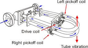
- U-shaped flow tube
- Sensor assembly
- Electronics unit

Principal of Operation
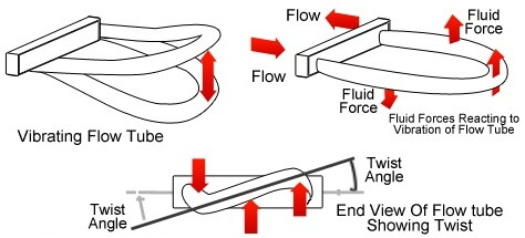
The flow is guided into the U-shaped tube. When an oscillating excitation force is applied to the tube causing it to vibrate, the fluid flowing through the tube will induce a rotation or twist to the tube because of the Coriolis acceleration acting in opposite directions on either side of the applied force.
For example, when the tube is moving upward during the first half of a cycle, the fluid flowing into the meter resists being forced up by pushing down on the tube. On the opposite side, the liquid flowing out of the meter resists having its vertical motion decreased by pushing up on the tube.
This action causes the tube to twist. When the tube is moving downward during the second half of the vibration cycle, it twists in the opposite direction.Theoretically, Coriolis force,
Fc= 2*m*w*V
m= mass (kg)
w= angular velocity (rad/s)
V= velocity (m/s)
‘U’ and ‘Ω’ shaped coriolis meters cause pressure drop as the flow is increased, resulting in permanent pressure loss.
Consequently, liquids near boiling point could introduced cavitation as the pressure across the meter drops below the vapour pressure of the liquid (forming of vapour bubbles).
As soon as the pressure recovers above the vapour pressure the bubbles impode.
Cavitation will cause the meter to malfunction and this should be avoided at all times.
The cross-section of the tube is normally smaller than the cross-section of the line pipe to increase the velocity (v) in order to create higher Coriolis forces. The latter holds good for Coriolis meters with straight measuring tubes as well. Consequently, the pressure drop will increase accordingly.
Coriolis mass flow meters will measure the mass flow rate and actual density accurately irrespective of the nature of the fluid as long as the flow is single phase and the fluid is homogeneous.
Being accurate, they are often used for custody transfer and critical reactor feed (ratio) control and also in streams where large variation in fluid composition will occur, which otherwise could not be measured.
A weak point is their requirement for Zero Adjustment at operation conditions. the zero adjustment is easily upset by not fully stress free installation of the meter.
The importance of zero adjustment is also demonstrated in the formula for the uncertainty in the reading of the meter, expressed as:
+/-[(zero stability/ flow rate)*100]% +/- x%
where x varies between 0.1 and 0.3% depending on design of the meter.


