
The mathematical relationship between fluid velocity and turbine tip velocity – assuming frictionless conditions – is a ratio defined by the tangent of the turbine blade angle:

For a 45 deg blade angle, the relationship is 1:1, with tip velocity equaling fluid velocity. Smaller blade angles (each blade closer to parallel with the fluid velocity vector) result in the tip velocity being a fractional proportion of fluid velocity.
Turbine tip velocity is quite easy to sense using a magnetic sensor, generating a voltage pulse each time one of the ferromagnetic turbine blades passes by.
Traditionally, this sensor is nothing more than a coil of wire in proximity to a stationary magnet, called a pickup coil or pick-off coil because it “picks” (senses) the passing of the turbine blades.
Magnetic flux through the coil’s center increases and decreases as the passing of the steel turbine blades presents a varying reluctance (“resistance” to magnetic flux), causing voltage pulses equal in frequency to the number of blades passing by each second.
It is the frequency of this signal that represents fluid velocity, and therefore volumetric flow rate.
In an electronic turbine flow meter, volumetric flow is directly and linearly proportional to pickup coil output frequency. We may express this relationship in the form of an equation:
![]()
Where,
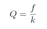
f = Frequency of output signal (Hz, equivalent to pulses per second)
Q = Volumetric flow rate (e.g. gallons per second)
k = “K” factor of the turbine element (e.g. pulses per gallon)
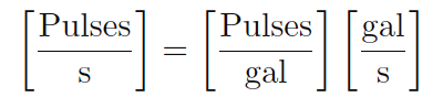
Dimensional analysis confirms the validity of this equation. Using units of GPS (gallons per second) and pulses per gallon, we see that the product of these two quantities is indeed pulses per second (equivalent to cycles per second, or Hz):
Using algebra to solve for flow (Q), we see that it is the quotient of frequency and k factor that yields a volumetric flow rate for a turbine flow meter:
The inherent linearity of a turbine flow meter is a tremendous advantage over nonlinear flow elements such as venturi tubes and orifice plates because this linearity results in a much greater turndown ratio for accurate flow measurement.
Contrasted against common orifice-type meters which are usually limited to turndown ratios of 4:1 at best, turbine meters commonly exceed turndown ratios of 10:1.
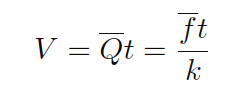
If pickup signal frequency directly represents volumetric flow rate, then the total number of pulses accumulated in any given time span will represent the amount of fluid volume (V ) passed through the turbine meter over that same time span.
We may express this algebraically as the product of average flow rate (Q), average frequency (f), k factor, and time:
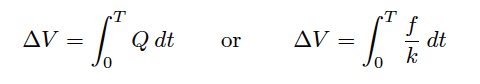
A more sophisticated way of calculating total volume passed through a turbine meter requires calculus, representing change in volume as the time-integral of instantaneous signal frequency and k factor over a period of time from t = 0 to t = T:
We may achieve approximately the same result simply by using a digital counter circuit to totalize pulses output by the pickup coil and a microprocessor to calculate volume in whatever unit of measurement we deem appropriate.
As with the orifice plate flow element, standards have been drafted for the use of turbine flowmeters as precision measuring instruments in gas flow applications, particularly the custody transfer of natural gas.
The American Gas Association has published a standard called the Report #7 specifying the installation of turbine flow meters for high-accuracy gas flow measurement, along with the associated mathematics for precisely calculating flow rate based on turbine speed, gas pressure, and gas temperature.
Pressure and temperature compensation is relevant to turbine flow meters in gas flow applications because the density of the gas is a strong function of both pressure and temperature.
The turbine wheel itself only senses gas velocity, and so these other factors must be taken into consideration to accurately calculate mass flow (or standard volumetric flow; e.g. SCFM).
In high-accuracy applications, it is important to individually determine the k factor for a turbine flow meter’s calibration. Manufacturing variations from flow meter to flow meter make precise duplication of k factor challenging, and so a flow meter destined for high-accuracy measurement should be tested against a “flow prover” in a calibration laboratory to empirically determine its k factor.
If possible, the best way to test the flow meter’s k factor is to connect the prover to the meter on site where it will be used. This way, the any effects due to the piping before and after the flowmeter will be incorporated in the measured k factor.