The valves will move up or down in response to changing vapour flow rates. At normal flow rate, the valve is roughly in the middle position.
At low vapour rates, the disk settles over the perforation and covers it to avoid liquid weeping.
The valves should be heavy enough to prevent excessive opening at low vapour flow rates. As the vapour rate is increased, the disk rises vertically.
The upward movement of the disk is restricted either by retaining legs or a cage. Weeping may result if excessive valve opening occurs prematurely. This will reduce the tray turn down.
In dirty or fouling services, the valves may get stuck due to the build-up of sludge or corrosion products around the valve. "Sticking " valves reduce the tray open area and can lead to premature flooding.
Valve trays offer larger operating range and greater capacity compared to sieve trays. In terms of cost, valve trays are more expensive than sieve trays.
4. Selection of Tray
The principle factors to consider when comparing the performance of bubble-cap, sieve and valve trays are:
Cost:
Bubble-caps are appreciably more expensive than sieve or valve trays, and the relative cost will depend on the material of construction used. Due to its simple design, sieve trays are normally the cheapest.
Operating Range:
This refers to the range of vapour and liquid rates over which the tray will operate satisfactorily. The ratio of the highest to the lowest flowrates is often referred to as the "turndown" ratio.
Bubble-cap trays have a positive liquid seal and can therefore operate efficiently at very low vapour rates. Sieve trays rely on the flow of vapours through the holes to hold the liquid on the tray, thus cannot operate at very low vapour rates.
Valve trays are intended to give greater flexibility than sieve trays at a lower cost than bubble-caps Thus, bubble-cap trays have the widest operating range, followed by valve tray, and sieve tray.
Pressure Drop:
This factor will be important in vacuum operations. The tray pressure drop will depend on the detailed design of the tray, but in general, sieve trays give the lowest pressure drop, followed by valves, with bubble-caps giving the highest.
Maintenance:
For dirty services, bubble-caps are not suitable as they are most susceptible to plugging. Sieve trays are the easiest to clean.
Summary
Sieve trays are the cheapest and are satisfactory for most applications.
Valve trays should be considered if the specified turn down ratio cannot be met with sieve trays.
Bubble-caps should only be used where very low vapour rates have to be handled and a positive liquid seal is essential at all flow rates.
Attributes | Bubble Cap/Valve | Sieve Tray |
Capacity | Moderately High | Higher than bubble cap at design, at low Thru' put performance drops as efficiency falls |
Efficiency | High | As high as bubble cap in the region of design, falls to unacceptable value |
Entrainment | Three times that of sieve tray | when capacity reduces < 60 % of 1/3rd of bubble cap tray. |
Flexibility | Most flexible design for high & low liquid rate. Allows positive drain of liquid from tray. Liquid head is maintained by weir. | Not suitable for column operating under variable load, falling < 60 % of design. Tray weeps liquid at low vapor rate. |
Attributes | Bubble Cap/valve | Sieve Tray |
Tray Spacing | 18 inch average. 24 to 36 inch for vacuum condition | Can be closer than bubble cap due to improved entrainment 15 inch average. 9, 10, 12 inch acceptable 20, 30 inch for vacuum |
Application | All service except extremely coking, polymer formation or other high fouling condition. | Systems where high capacity design rates to be maintained. Handles suspended solid particles. |
Parameter | Sieve | Floating | Fixed |
Turndown | Less | Good | Better than sieve but less than floating valves |
Pressure Drop | Less | High | Less than floating valves |
Capacity | Less than Floating valves | Good | Better than sieve and floating valves |
Fouling Services | Big Hole sieves depending on process conditions | Not suitable due to sticking of valves | Best |
5. Down comers
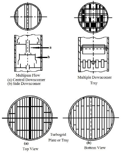
Plates without downcomers
These are generally flat circular plates of a diameter slightly smaller than the internal diameter of the column, located with suitable spacing from the bottom to the top of the column they are provided with a large number of holes of slats through which the liquid and the vapor pass the turbo grid is a flat plate with long rectangular slats the grid can also be formed by closely spaced parallel bars located in one circular plane in stead of a single flat plate.
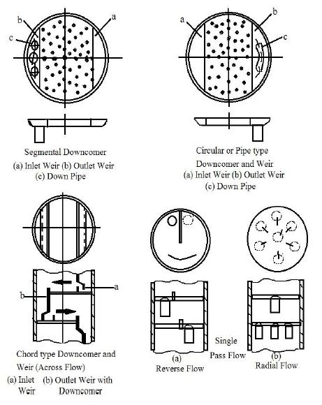
Plate with downcomers
These are circular flat plates or trays with provision passage known as down comers for the downwards flow of the liquid, the down comers area for each plate will be generally limited to 10% of the total area of the plate. Various arrangement of down comers, weirs and contacting devices are adopted for handling liquid and vapors.
6. Other Column Internals
Internals common to Tray and Packed Columns
4 items shall be discussed here:
(a) Liquid Distributor
(b) Liquid Re-distributor
(c) Vapour Distributor
(d) Mist Eliminator (Demister)
Liquid distributor
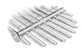
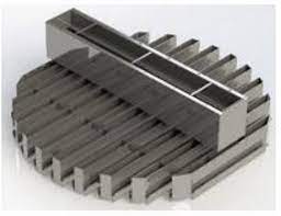
As the name implies, its function is to distribute liquid evenly across the tray or packings (e.g. at the reflux inlet). However, some degree of maldistribution is unavoidable, as liquid can only be divided into a limited number of streams. From these point sources the liquid spreads.
Liquid distributors are generally classified into pressure distributors (e.g. ladder pipe, spray) and gravity distributors (e.g. weir type and orifice type). 2 designs are shown below: left for a typical column, and right for a large diameter column.
 |
| piping orifice distributor |
 |
| through type distributor |
Liquid and/or vapour re-distributor
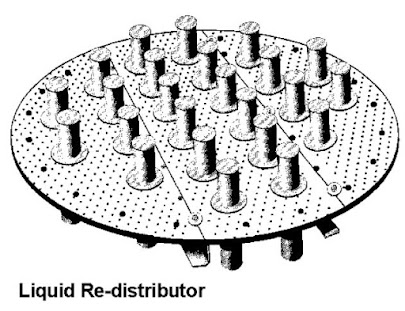
These are used whenever an intermediate liquid feed needs to be introduced into a packed column or between packed sections (of tall columns), or pump-around return to a tray column, or wherever liquid re-distribution is required. Examples include the orifice re-distributors and weir re-distributors.
Besides re-distribution of liquid, the device also helps to distribute vapour flow in the column. Re-distributors also help to mix and equalize the liquid and vapour composition throughout the column cross section. An example is shown in the Figure below.
Vapour Distributor
These devices are required for introduction of vapour feed from the bottom of the column, or for the reboiler vapour return to the column. A sparger pipe or chimney tray or vapour distributor with support may be used. Some act as support for the packed bed as well.
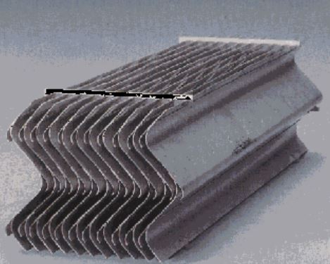
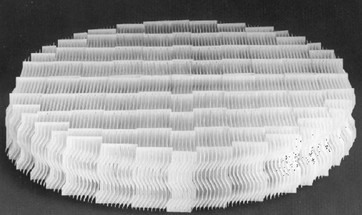
Demister / mist eliminator
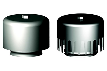
This device is located at the top of the column before the vapour leaves. It removes liquid droplets entrained in the vapour stream before the stream leaves the top of the column. 2 designs are shown below on left and right respectively.
7. Other Packed Column Internals
The following internals are unique to packed columns:
(a) packing support,
(b) retaining devices (Hold-down Plate or Bed Limiter)
Packing support
The main function of packing support as shown in the Figure below is to physically support the packed bed and prevent the downward migration of packing pieces.
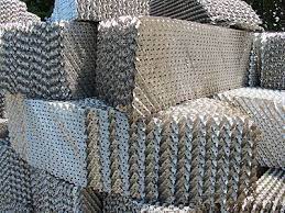
Packing support should have sufficient open area to permit unrestricted flow of liquid and vapour. Grid supports and corrugated supports are commonly used. A layer of structured packing can sometimes be used as support.

Retaining devices
The 2 types are shown below:
- Hold-down plates
- Bed limiter
Hold-down plates are used with ceramic or carbon random packing to prevent fluidization of the packings and restrict packing movement, which may break the packing particles.
The hold-down plate rests directly on the packing. It is not used with metal or plastic packings to avoid crushing the metal or compressing the plastic.
For these packing materials, bed limiter is used. Bed limiters do not rest on packing, instead they are secured to the column wall by support ring or bolting clips.
Fluidisation caused upset in the packing, and the packing particles may settle unevenly, thus promoting maldistribution, which in turn reduces column efficiency and/or capacity.
8. Column Top and Intermediate Inlets/Outlets Arrangements
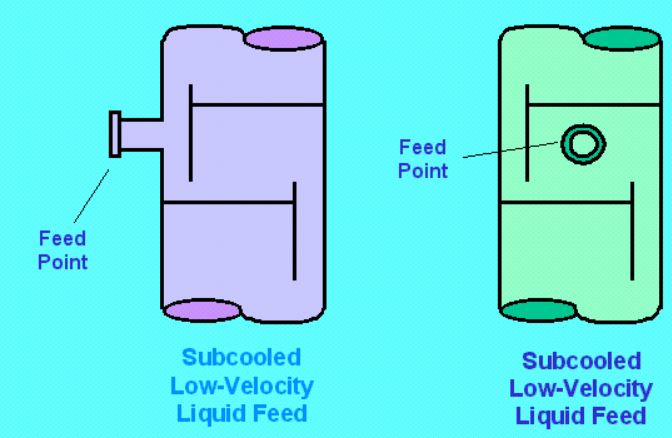
Reflux Inlet / Top Feed Inlet
Intermediate Feed Inlet
9. Downcomer Trap out & Chimney Tray
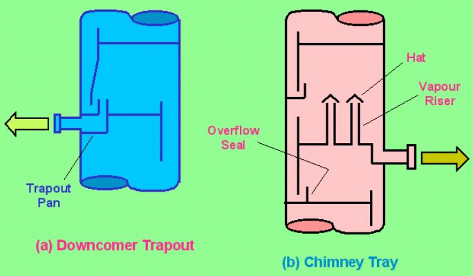
Downcomer trap outs are mainly used for partial liquid draw-off from tray columns. Downcomer trap outs seldom provide sufficient residence time for vapour disengagement, and the venting process must be completed downstream of the column outlet.
Trap out must be sealed to prevent vapour from flowing up the downcomer, as showed in the Figure below (left).
And alternative to downcomer trap out is the chimney tray, shown in the Figure below (right). In a packed tower, it is also used as liquid collector or vapour distributor.
The advantage of chimney trays is that they provide greater time for vapour disengagement, but consume more column height. The other disadvantage is their relatively high pressure drop.
10. Vapour Outlet
Vapour outlets poses far less problem than liquid outlets. The prime consideration is avoiding the presence of entrained liquid droplets in the vapour streams leaving the columns. Mist eliminators can be installed above the top tray or a separate knock-out drum can be used.
Low points in the vapour lines should be avoided as these tend to trap liquid and accumulate liquids. The accumulated liquid can back-pressure the column causing instability and erratic operation, or can create a slug flow into downstream units.
Vapour outlet lines should be sloped (i.e. self-draining) either back to the column or into a downstream vessel.
11. Column Bottom Arrangement
Bottom Feed or Reboiler Return Inlet
Bottom feed and reboiler return inlets should never be submerged below the liquid level. Column of liquid above the submerged inlet can vary in height, and under certain conditions, slugs of liquid and vapour can be blown up the column and lift ("bump") trays off their support or packing support plates.
Inlets below the liquid level can also be responsible for excessive entrainment and premature flooding.
The section of column wall directly opposite a bottom inlet nozzles often prone to corrosion and erosion attacks, especially for cases involving high inlet velocities, small column diameter and corrosive chemicals.
These effects can be reduced by installing an impingement plate. The inlet should also not impinge on bottom seal pan, seal pan overflow or bottom downcomer.
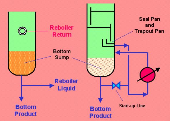
3 arrangements are commonly used for column bottom:
Unbaffled arrangement - where both bottom product and reboiler liquid are withdrawn from a common bottom sump.
Baffled arrangement - where the space at the bottom of the column is divided into a bottom draw-off sump and a reboiler feed sump by a preferential baffle. See the Figure below.
Once-through reboiler arrangement - where the reboiler liquid is withdrawn from the bottom downcomer or from a chimney tray located above the bottom sump. See the Figure below.
Unbaffled arrangement has the advantage of simplicity and low cost. They are preferred in small column (less than 3-ft diameter) where baffles are difficult to inspect and maintain.
They are used for kettle reboilers because the bottom product is withdrawn from the reboiler surge compartment, not from the column bottom sump. They are also used with forced-circulation reboilers as the large circulation rate makes it difficult to achieve a steady liquid overflow across the baffle.
Because it is difficult to deflect liquid raining from a packed bed above the reboiler sump into the reboiler side of the preferential baffle, unbaffled arrangement is normally used in packed column.
Baffled or once-through arrangements are usually preferred with thermosiphon reboilers in large columns (more than 3-ft diameter). They can supply a constant liquid head to the reboilers, and maximise bottom sump residence time when vapour disengagement is the main consideration.
Bottom Outlet
The main consideration is to achieve the required phase separation between vapour and liquid, and providing the required surge capacity. Arrangements such as bottom sumps, chimney trays, and surge drums are usually designed for avoiding the presence of vapour in the liquid outlet.
On the other hand, downcomer trapouts are usually designed to allow for the presence of vapour.Sample plant picture
Presence of vapour in liquid outlet lines can cause pump cavitation, erosion, column instability, etc. Some of the common causes are:
Insufficient residence time for vapour disengagement from the liquid. Liquid arriving the pan or sump from which it is withdrawn almost always contains entrained vapour bubbles.
Frothing (waterfall pool effect) is caused by impact of falling liquid on liquid surface in the sump or draw pan. Frothing is a far greater problem in tray column sumps (where liquid fall resembles a waterfall) than in packed column sumps (where liquid fall is more like rain).
Vortexing occurs because of intensification of swirling motion as liquid converges towards an outlet. Vortexing promotes entrainment of vapour into the draw-off line. Vortex breakers can be installed to prevent vortexing.


