Basics of Ultrasonic Flow meters
The term ‘ultrasonic’ is used to describe pressure waves at frequencies higher than the human ears can detect.
The velocity of the sound waves in the fluid is the same as the velocity of sound in the fluid. If an ultrasonic beam is transmitted across a pipeline at an angle to the flow direction, the time taken for the pulse to reach the receiver is a function of the flow velocity of the fluid, as well as the velocity of sound in the fluid.
Ultrasonic Flow Meters Working Principle
Ultrasonic flow meters operate using the transit-time differential method. The Transit-time differential measurement is based on a simple physical fact.
Imagine two canoes crossing a river on the same diagonal line, one with the flow and the other against the flow. The canoe moving with the flow needs much less time to reach the opposite bank.
Ultrasonic waves behave exactly the same way. A sound wave travelling in the direction of flow of the product is propagated at a faster rate than one travelling against the flow (vAB > vBA).
Transit times tAB and tBA are measured continuously. The difference (tBA – tAB) in time travelled by the two ultrasonic waves is directly proportional to the mean flow velocity (vm).
Where,
- tAB is Time required for ultrasonic wave to travel from Sensor A to B sensor
- tBA is Time required for ultrasonic wave to travel from Sensor B to A sensor
Thus, this type of flow meter operates on the principle of transit time differences. An acoustic signal (ultrasonic) is transmitted from one sensor to another.
This can be either in the direction of flow (downstream) or against the direction of flow (upstream). The time (transit) that the signal requires to arrive at the receiver is then measured.
According to physical principles, the signal sent against the direction of flow requires longer to return than the signal in the direction of flow.
The difference in the transit time is directly proportional to the velocity of flow.
v ≈ Δ t
v = k Δ t
w here k is a constant
Flow rate is thus,
Q = v •. A
where,
v = flow velocity
Δt = transit time difference between the signal in the direction of flow and against the direction of flow
Q = volumetric flow
A = pipe cross-sectional area
The mathematical relationship between fluid velocity (v) and the Doppler frequency shift (Δf) is as follows, for fluid velocities much less than the speed of sound through that fluid (v << c):
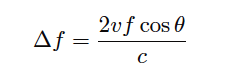
Where,
Δf = Doppler frequency shift
v = Velocity of fluid (actually, of the particle reflecting the sound wave)
f = Frequency of incident sound wave
θ = Angle between transducer and pipe centerlines
c = Speed of sound in the process fluid
Formulas Calculations check here
Transmitter and receiver roles are constantly switched by electronics. Ultrasonic pulses traveling in the direction of the flow, travel path between transducers in a shorter period of time than pulses traveling against the flow.
This is because the flow speeds up pulses traveling downstream but slows down pulses traveling upstream. The equation is;
Multiple traverse Ultrasonic Flow meter
A multiple-transverse configuration consists of two transducers mounted on the pipe so that the signal traverses the fluid two or more times before reaching the other transducer (figure 2). The walls of the pipe reflect the ultrasonic signal in order to maintain at 45 angle.
This allows the signal to remain in the fluid longer, increasing the effective length ( L ) of the signal path, and thus increasing accuracy.
The number of times the signal can traverse through the fluid depends on factors such as transducer frequency, pipe size, pipe wall condition, and the fluid being measured.
Features:
- Easy to carry;
- Low maintenance;
- Can only be used to measure cleaning liquids;
- Not subject to pipe diameter restrictions;
- No flow obstruction measurement, no additional pressure loss.
Fluid velocity is measured by sending an ultrasonic pulse from an upstream transducer to a downstream transducer and back again. The measured difference in the amount of time that each pulse takes to traverse the pipe is directly proportional to the mean fluid velocity.
ultrasonic flow meters use this measured velocity to calculate the liquid flow rate based on user-entered information about the process application.
Types of Ultrasonic Flow Meter
Ultrasonic flow meters available in the market are radar, Doppler velocity, ultrasonic clamp-on, and ultrasonic level.
Doppler velocity type meters use reproduced ultrasonic noise to calculate the liquid’s velocity.
Radar type meter employs microwave technology for transmitting small pulses to reflect off a flowing surface back to the sensor for deciding velocity.
Ultrasonic clamp-on type meter is ideal for applications wherever accessing the pipe is difficult otherwise not possible.
Ultrasonic level type meter is ideal for determining the fluid level in both open & closed channels.
Factors Affecting Performance and Accuracy
A. Surface Condition –
Loose or flaking scale, rust, corrosion or dirt on the outside surface of a test piece will interfere with the coupling of sound energy from the transducer into the test material.
Thus, any loose debris of this sort should be cleaned from the specimen with a wire brush or file before measurements are attempted.
Generally it is possible to make corrosion measurements through thin layers of rust, as long as the rust is smooth and well bonded to the metal below.
Some very rough cast or corroded surfaces may have to be filed or sanded smooth in order to insure proper sound coupling. It may also be necessary to remove paint if it has been applied in thick coats, or if it is flaking off the metal.
While it is often possible to make corrosion measurements through thin coats of paint (on the order of a few thousandths of an inch or 0.1 – 0.2mm), thick paint will attenuate signals or possibly create false echoes, causing inaccurate measurements.
Severe pitting on the outside surface of a pipe or tank can be a problem. On some rough surfaces, the use of a gel or grease rather than a liquid couplant will help transmit sound energy into the test piece.
In extreme cases it will be necessary to file or grind the surface sufficiently flat to permit contact with the face of the transducer.
In applications where deep pitting occurs on the outside of a pipe or tank it is usually necessary to measure remaining metal thickness from the base of the pits to the inside wall.
There are sophisticated ultrasonic techniques utilizing focused immersion transducers that can measure directly from the base of the pit to the inside wall, but this is generally not practical for field work.
The conventional technique is to measure unfitted metal thickness ultrasonically, measure pit depth mechanically, and subtract the pit depth from the measured wall thickness.
Alternately, one can file or grind the surface down to the base of the pits and measure nominally.
As with any difficult application, experimentation with actual product samples is the best way to determine the limits of a particular gage/transducer combination on a given surface.
B. Transducer Positioning/Alignment –
For proper sound coupling the transducer must be pressed firmly against the test surface.
On small diameter cylindrical surfaces such as pipes, hold the transducer so that the sound barrier material visible on the probe face is aligned perpendicular to the center axis of the pipe.
While firm hand pressure on the transducer is necessary for good readings, the probe should never be scraped along or twisted against a rough metal surface. This will scratch the face of the transducer and eventually degrade performance.
The safest technique for moving a transducer along a rough surface is to pick it up and reposition it for each measurement, not to slide it along.
Remember that an ultrasonic test measures thickness at only one point within the beam of the transducer, and that in corrosion situations wall thicknesses often vary considerably.
Test procedures usually call for making a number of measurements within a defined area and establishing a minimum and/or average thickness.
Ideally, data should be taken at increments no greater than half the diameter of the transducer, to insure that no pits or other local variations in wall thickness are missed.
It is possible that on some severely corroded or pitted materials there will be spots where readings cannot be obtained.
This can happen when the inside surface of the material is so irregular that the sound energy is scattered rather than being reflected back to the transducer.
The lack of a reading may also indicate a thickness outside the range of the transducer and instrument being used.
Generally, an inability to obtain a valid thickness reading at a particular point on a test specimen could be a sign of a seriously degraded wall which may warrant investigation by other means.
C. Calibration –
The accuracy of measurements are only as good as the accuracy and care with which the gauge has been calibrated.
It is essential that the velocity and zero calibrations be performed whenever the transducer is changed or you have a reason to doubt the accuracy of the readings.
Periodic checks with samples of known thicknesses are recommended to verify that the gauge is operating properly.
D. Taper or Eccentricity –
If the contact surface and the back surface are tapered or eccentric with respect to each other, the return echo again becomes distorted and the accuracy of measurement is diminished.
E. Acoustic Properties of the Material –
There are several conditions found in engineering materials that can severely limit the accuracy and thickness range that can be measured.
1. “ Sound Scattering ” –
In some materials, notably certain types of cast stainless steel, cast irons, and composites, the sound energy is scattered from individual crystallites in the casting or from dissimilar materials within the composite.
This effect reduces the ability to discriminate a valid return echo from the back side of the material and limits the ability to gauge the material ultrasonically.
2. Velocity Variations –
A number of materials exhibit significant variations in sound velocity from point-to-point within the material.
Certain types of cast stainless steels and brass exhibit this effect due to a relatively large grain size and the anisotropy of sound velocity with respect to grain orientation.
Other materials show a rapid change in sound velocity with temperature. This is characteristic of plastic materials where temperature must be controlled in order to obtain maximum precision in the measurement.
3. Sound Attenuation or Absorption –
In many organic materials, such as low density plastics and rubber, sound is attenuated very rapidly at the frequencies used in normal ultrasonic thickness gauging.
Therefore, the maximum thickness that can be measured in these materials is often limited by sound attenuation.
Pros and Cons of Ultrasonic Flow Meters

Advantages of Ultrasonic Flow Meter
The advantages are
It does not block the path of liquid flow.
The o/p of this meter is different for density, viscosity & temperature of the liquid.
The flow of liquid is bidirectional
The dynamic response of this meter is good.
The output of this meter is in analog form
Conservation of energy
It is appropriate for huge quality flow measurement
It is handy to fit and maintain
Versatility is good
There is no contact to liquid
There is no leakage risk
There are no moving parts, pressure loss
High accuracy
Disadvantages of Ultrasonic Flow Meter
The disadvantages are
It is expensive as compared with other mechanical flow meters.
Design of this meter is complex
Auditory parts of this meter are expensive.
These meters are complicated as compared with other meters, thus it requires specialists for maintaining and repairing these meters
It cannot measure cement or concrete pipes one they rusted.
It doesn’t work once the pipe contains holes or bubbles in it
Can’t measure cement/concrete pipe or pipe with such material lining
Applications
The applications of ultrasonic flow meters include the following.
These meters are used in wastewater and dirty liquid applications
These meters are used wherever chemical compatibility, less maintenance, and low-pressure drop are required.
These meters are used to measure the velocity of a liquid through ultrasound to analyze volume flow.
These meters measure the disparity between the transit time of ultrasonic pulses which transmits with the direction of liquid flow
The applications of these meters range from process to custody flow
This is one kind of device for volumetric flow measurement for liquids as well as gases.
These are excellent alternatives for both vortex & electromagnetic flowmeters.
Read more about "Flowmeters" from Industrial Guide - Click here
Thanks for reading - Ultrasonic Flow meter
Naitik Patel
Industrial Guide


