When a fluid moves with high Reynolds number past a stationary object (a “bluff body”), there is a tendency for the fluid to form vortices on either side of the object. Each vortex will form, then detach from the object and continue to move with the flowing gas or liquid, one side at a time in alternating fashion.
This phenomenon is known as vortex shedding, and the pattern of moving vortices carried downstream of the stationary object is known as a vortex street.
It is commonplace to see the effects of vortex shedding on a windy day by observing the motion of flagpoles, light poles, and tall smokestacks.
Each of these objects has a tendency to oscillate perpendicular to the direction of the wind, owing to the pressure variations caused by the vortices as they alternately form and break away from the object:
Vortex shedding
This alternating series of vortices was studied by Vincenc Strouhal in the late nineteenth century and later by Theodore von K´arm´an in the early twentieth century.
It was determined that the distance between successive vortices downstream of the stationary object is relatively constant, and directly proportional to the width of the object, for a wide range of Reynolds number values (Note). If we view these vortices as crests of a continuous wave, the distance between vortices may be represented by the symbol customarily reserved for wavelength: the Greek letter “lambda” (λ).
Note : It is important to note that the vortex-shedding phenomenon ceases altogether if the Reynolds number is too low.
Laminar flow produces no vortices, but rather stream-line flow around any object placed in its way.
Vortex Flow Meter
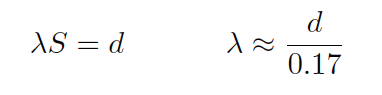
The proportionality between object width (d) and vortex street wavelength (λ) is called the Strouhal number (S), approximately equal to 0.17:
If a differential pressure sensor is installed immediately downstream of the stationary object in such an orientation that it detects the passing vortices as pressure variations, an alternating signal will be detected:
The frequency of this alternating pressure signal is directly proportional to fluid velocity past the object, since the wavelength is constant.
This follows the classic frequency-velocity-wavelength formula common to all traveling waves (λf = v).
Since we know the wavelength will be equal to the bluff body’s width divided by the Strouhal number (approximately 0.17), we may substitute this into the frequency-velocity-wavelength formula to solve for fluid velocity (v) in terms of signal frequency (f) and bluff body width (d).

Thus, a stationary object and pressure sensor installed in the middle of a pipe section constitute a form of flow meter called a vortex flow meter.
Like a turbine flow meter with an electronic “pickup” sensor to detect the passage of rotating turbine blades, the output frequency of a vortex flow meter is linearly proportional to volumetric flow rate.
The pressure sensors used in vortex flow meters are not standard differential pressure transmitters, since the vortex frequency is too high to be successfully detected by such bulky instruments.
Instead, the sensors are typically piezoelectric crystals. These pressure sensors need not be calibrated, since the amplitude of the pressure waves detected is irrelevant.
Only the frequency of the waves matter for measuring flow rate, and so nearly any pressure sensor with a fast enough response time will suffice.
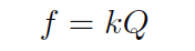
Like turbine meters, the relationship between sensor frequency (f) and volumetric flow rate (Q) may be expressed as a proportionality, with the letter k used to represent the constant of proportionality for any particular flowmeter:
Where,
f = Frequency of output signal (Hz)
Q = Volumetric flow rate (e.g. gallons per second)
k = “K” factor of the vortex shedding flow tube (e.g. pulses per gallon)
Note : that if flow rate is to be expressed in units of gallons per minute as is customary, the equation must contain a factor for minutes-to-seconds conversion: f = kQ/60
This means vortex flow meters, like electronic turbine meters, each have a particular “k factor” relating the number of pulses generated per unit volume passed through the meter.
Counting the total number of pulses over a certain time span yields total fluid volume passed through the meter over that same time span, making the vortex flow meter readily adaptable for “totalizing” fluid volume just like turbine meters.
The direct proportion between vortex frequency and volumetric flow rate also means vortex flow meters are linear-responding instruments just like turbine flow meters.
Unlike orifice plates which exhibit a quadratic response, turbine and vortex flow meters alike enjoy a wider range (turndown) of flow measurement and do not require special signal characterization to function properly.
Note :This k factor is empirically determined for each flow meter by the manufacturer using water as the test fluid (a factory “wet-calibration”), to ensure optimum accuracy.
Since vortex flow meters have no moving parts, they do not suffer the problems of wear and lubrication facing turbine meters. There is no moving element to “coast” as in a turbine flow meter if fluid flow suddenly stops, which means vortex flow meters are better suited to measuring erratic flows.
A significant disadvantage of vortex meters is a behavior known as low flow cutoff, where the flow meter simply stops working below a certain flow rate.
The reason for this is laminar flow: at low flow rates (i.e. low Reynolds number values) the effects of fluid viscosity overwhelm fluid momentum, preventing vortices from forming.
This cessation of vortices causes the vortex flowmeter to register absolutely no flow at all even when there is still some (laminar) flow through the pipe.
At high flow rates (i.e. high Reynolds number values), fluid momentum is enough to overcome viscosity and produce vortices, and the vortex flow meter works just fine.
The phenomenon of low-flow cutoff for a vortex flow meter at first seems analogous to the minimum linear flow limitation of a turbine flow meter.
However, vortex flow meter low-flow cutoff is actually a far more severe problem. If the volumetric flow rate through a turbine flow meter falls below the minimum linear value, the turbine continues to spin, albeit slower than it should.
If the volumetric flow rate through a vortex flow meter falls below the low-flow cutoff value, however, the flow meter’s signal goes completely to zero, indicating no flow at all. This idiosyncrasy makes vortex flow meters entirely unsuitable in applications where the desired flow measurement range extends all the way down to zero.
Vortex Flow Transmitter
The next two photographs show close-up views of the flowtube assembly, front (left) and rear (right):
Vortex Flow Sensor
Vortex flow meters, like other velocity-based meters, are affected by large-scale turbulence in the fluid stream and therefore require some length of straight pipe both upstream and downstream of the flow meter to properly characterize the flow.
It is typical to install vortex flow meters with 10 pipe diameters of straight-length pipe upstream and 5 pipe diameters downstream.
Working Principle of Vortex Flow Meter
Vortex Meters can be used for a wide range of fluids, i.e. liquids, gases and steam. They are to be seen as first choice, subject to verification to cover the requirements of a particular application. Vortex Flow Animation
Vortex meters are essentially frequency meters, since they measure the frequency of vortices generated by a “bluff body” or”shedder bar”.
Vortices will only occur from a certain velocity (Re-number) on-wards, consequently vortex meters will have an elevated zero referred to as the “cut-off” point. Before the velocity becomes nil, the meter output will be cut to zero.
At a certain back-flow (above cut off point) some vortex meters could produce an output signal, which could lead to a false interpretation.
Vortex meters are actual volume flow meters, like orifice meters. These being intrusive meters like orifice meters, will cause the pressure drop as flow is increased, resulting in a permanent loss. consequently, liquids near their boiling point, could introduce cavitation as the pressure across the meter drops below the vapour pressure of the liquid.
As soon as the pressure recovers above the vapour pressure the bubbles will impode. cavitation causes the meter to malfunction and should be avoided at all times.
Principle
A fluid flowing with a certain velocity and passing a fixed obstruction generates vortices. The generation of vortices is known as Karman’s Vortices and culmination point of vortices will be approx. 1.2D downstream of bluff body.
Strouhal discovered that as soon as a stretched wire starts vibrating in an air flow, frequency will be directly proportional to air velocity,Vortex Flow meter
St= f*d/V0 (without dimension)
St= Strouhal’s number
f=frequency of wire
d=diameter of wire
V0= Velocity
This phenomena is called “vortex shedding” and the train of vortices is known as “Karman’s Vortex street”.
The frequency of vortex shedding is a direct linear function of fluid velocity and frequency depends upon the shape and face width of bluff body. Since the width of obstruction and inner diameter of the pipe will be more or less constant, the frequency is given by the expression-
f=(St*V)/c*D
f= vortex frequency, Hz
St=strouhal’s number, dimention less
V=Fluid velocity at the sheddar bar, m/s
D=Inner diameter of the pipe, m
c=constant (ratio d/D)
d= Face width of sheddar bar, m
The pressure loss gradient across the vortex meter will have a similar shape to that of an orifice meter. the lowest point in pressure will be at the sheddar bar (comparable to vena contracta for orifice meter). downstream of this point of pressure will recover gradually, finally resulting in permanent pressure loss. To avoid cavitation, the pressure loss at vena-contracta is of interest.
The minimum back pressure required to ensure cavitation doesn’t occur is:
Pmin=3.2*Pdel + 1.25*Pv
Pmin= minimum required pressure at five pipe diameters downstream of the flow meter in bar
Pdel= calculated permanent pressure loss in bar
Pv= vapour pressure at operating temperature in bar
Remember- for most vortex meters d/D will have range, 0.22 – 0.26, & frequency od vortices will depend on sizre of meter, larger the meter, lower the frequency. So the maximum diameter of vortex meter is restricted, because resolution of meter could become a problem.for control purposes.
To overcome this problem, on-board digital multipliers are used which will multiply the vortex frequency without additional error.
Frequency Sensing Principle
Piezo-electrical Sensors- a pair of piezo-electrical crystals is built into the sheddar bar. as the sheddar bar will be subject to alternating forces caused by shedding frequency, so will the piezo-crystals.
Variable capacitance Sensors- a pair of variable capacitance sensors is built into the sheddar bar. As the sheddar bar will be subject to alternating micro movements caused by forces as a result of the shedding frequency, the capacitors will change their capacitance accordingly.
Performance of Vortex meters is influenced by
change in sheddar bar geometry owning to erosion
change in sheddar bar geometry owning to deposits, i.e. Wax
corrosion of upstream piping
change in position of sheddar bar if not properly secured
Hydraulic noise.
In-general votex meter will consist of following electonics part-
pick-up elements, AC-pre amplifiers, AC-amplifier with filters, Noise abatement features, Schmitt Trigger, Microprocessor
Features
The vortex shedding meter provides a linear digital (or analog) output signal without the use of separate transmitters or converters, simplifying equipment installation. Meter accuracy is good over a potentially wide flow range, although this range is dependent upon operating conditions.
The shedding frequency is a function of the dimensions of the bluff body and, being a natural phenomenon, ensures good long term stability of calibration and repeatability of better than ±0.15% of rate. There is no drift because this is a frequency system.
The meter does have any moving or wearing components, providing improved reliability and reduced maintenance. Maintenance is further reduced by the fact that there are no valves or manifolds to cause leakage problems. The absence of valves or manifolds results in a particularly safe installation, an important consideration when the process fluid is hazardous or toxic.
If the sensor utilized is sufficiently sensitive, the same vortex shedding meter can be used on both gas and liquid. In addition, the calibration of the meter is virtually independent of the operating conditions (viscosity, density, pressure, temperature, and so on) whether the meter is being used on gas or liquid.
The vortex shedding meter also offers a low installed cost, particularly in pipe sizes below 6 in. (152 mm) diameter, which compares competitively with the installed cost of an orifice plate and differential pressure transmitter.
The limitation include meter size range. Meters below 0.5 in. (12 mm) diameter are not practical, and meters above 12 in. (300 mm) have limited application due their high cost compared to an orifice system and their limited output pulse resolution.
The number of pulses generated per unit volume decreases on a cube law with increasing pipe diameter. Consequently, a 24 in. (610 mm) diameter vortex shedding meter with a typical blockage ratio of 0.3 would only have a full scale frequency output of approximately 5 Hz at 10 ft/s (3 m/s) fluid velocity.
Selection and Sizing :
As the first step in the selection process, the operating conditions (process fluid temperature, ambient temperature, line pressure, and so on) should be compared with the meter specification.
The meter wetted materials (including bonding agents) and sensors should then be checked for compatibility with the process fluid both with regard to chemical attack and safety. On oxygen, for example, non ferrous material should be used avoided or approached with extreme caution. The meter minimum and maximum flow rates for the given application should then be established.
The meter minimum flow rate is established by a Reynolds number of 10,000 to 10,500, the fluid density, and a minimum acceptable shedding frequency for the electronics. The maximum flow rate is governed by the meter pressure loss (typically two velocity heads), the onset of cavitation with liquids, and sonic velocity flow (choking) with gases.
Consequently, the flow range for any application depends totally upon the operating fluid viscosity, density, and the vapour pressure, and the applications maximum flow rate and line pressure.
On low viscosity products such as water, gasoline, and liquid ammonia, and with application maximum velocity of 15 ft/s (4.6 m/s), vortex shedding meters can have a rangeability of about 20:1 with a pressure loss of approximately 4 PSIG (27.4 kPa).
The meter’s good (“of rate”) accuracy and digital linear output signal make its application over wide flow ranges a practical proposition. The rangeability declines proportionally with increase in viscosity, decrease in density, or reductions in the maximum flow velocity of the process. Vortex shedding meters are therefore unsuitable for use on high viscosity liquids.
Vortex Meter Advantages
- Vortex meters can be used for liquids, gases and steam
- Low wear (relative to turbine flow meters)
- Relatively low cost of installation and maintenance
- Low sensitivity to variations in process conditions
- Stable long term accuracy and repeatability
- Applicable to a wide range of process temperatures
- Available for a wide variety of pipe sizes
Vortex Flow Meter Limitations
- Not suitable for very low flow rates
- Minimum length of straight pipe is required upstream and downstream of the vortex meter
Vortex Flow Meter Applications
Vortex flow meters are suitable for a variety of applications and industries but work best with clean, low-viscosity, medium to high speed fluids.
Applications
- Custody transfer of natural gas metering
- Steam measurement
- Flow of liquid suspensions
- General water applications
- Liquid chemicals & pharmaceuticals
Installation
Vortex meters are installed directly in the process piping and are normally supported by the piping. They may be installed in any orientation. A vortex meter should be installed so that the meter body is not subjected to piping strain.
In liquid applications, the piping should be arranged so that the meter is kept full. Block and bypass valves should be provided when operating conditions do not permit shutdown.
Vortex meters are sometimes damaged during the start-up of new installations as a result of debris in the line. The line should be flushed and hydrostatically tested before the meter is installed.
Since the velocity profile is critical, it is imperative that gaskets not protrude into the flow stream when flanged meters are installed. Field calibration of vortex meters is limited to electrically spanning the converter or, on a pulse-output type, adjusting the scaling factor.
Vortex flow meters offer many advantages for flow measurement including easy installation without impulse lines, no moving parts to maintain or repair, less leak potential, and a wide flow turndown range. Vortex meters also offer very low power consumption, allowing for use in remote areas.
Additionally, Vortex meters are unique in that they can accommodate liquids, gasses, steam, and corrosive applications. Vortex flowmeters are also able to withstand high process pressures and temperatures.
Vortex Meters Operating Conditions
Here we shall see which type of vortex meter to use in different operating conditions and services.

Thanks for reading - Vortex Flow Meter.
Naitik Patel
Industrial Guide