Couplings are used to connect Motor or other driving force to equipment's like Pump, Reactor, Compressor Etc. Couplings transfer angular rotation and torque. There are several types of coupling with specific advantages and disadvantages.
Types of couplings
Rigid coupling
- Sleeve coupling [Muff coupling]
- Clamp coupling [Split coupling/compression coupling]
- Flange Coupling
Flexible coupling
- Bushed Pin Flexible Coupling
- Oldhams coupling
- Universal coupling
[ads id="ads1"]
Why couplings are required?
There are several reasons that needs coupling between motor and equipment.
- Motor generally owned by electrical department and Equipment is owned by mechanical department.
- Shafts are generally available in 7 meters length, More lengths are having transport issues.
- Motor and equipment are sold in market as an individual.
- Maintenance or failure of Equipment which requires more time of maintenance than replacement are requires replacement of Motor or Equipment for restoration and quick start up, So coupling of equipment could decouple replacement and restart process.
- Coupling provides proper alignment between motor and equipment.
Signs of good coupling
- Good coupling is easy to couple / decouple and alignment.
- It should reduce or absorb transmission shock between motor or equipment
- Less torque drop in operation.
- Coupling should hold shafts in aligned position.
Rigid Coupling
Sleeve coupling [Muff coupling]
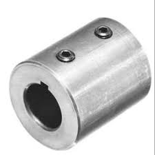
Sleeve coupling is simplest type coupling in rigid coupling. It's structure of hollow cylinder whose inner diameter is same of shaft's diameter. Placement of coupling is on the shafts using gib head key.
Torque is transmitted from motor to equipment through gib key and coupling.
[ads id="ads1"]
Advantages
Simple in design, It has only two parts coupling and gib key.
Cost economic
Compact in design so transportation becomes easier.
No projecting parts so it's safe to use.
Disadvantages
It has no shock absorbing parts like spider so its make noise and vibrations.
Difficult of to assemble and disassemble dew to it's bolting
It is rigid coupling so not offering misalignment compensation.
Application
In line shafts in small pumps
2. Clamp coupling [Split coupling/compression coupling]
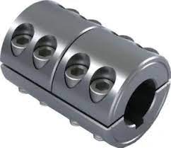
Clamp coupling is made of two halves and placed on shaft. after placement it is fitted with bolts.The Shaft made about and connected to each other with bolts and single key fitted directly with key ways given at shafts.
Bolts are generally two, four, six or eight as per length. Nuts are necessary for fitting muff castings. This type of coupling is used for heavy duty couplings and moderated speed.
[ads id="ads1"]
Advantages
Position of shafts not need to be change during decoupling.
Disadvantages
It is not used in High speed operations.
Application
Used where shafts are in line in small to moderated sze.
3. Flange coupling
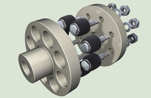
Flange coupling applied in that cases where motor and equipment has coupling. Faces are forged at right angle.
Credits - IndiaMart
One flange is projected part and other is corresponding part. This arrangement helps to adjust shaft in line and stay in alimented. Flanges have spider adaptable design. Both flanges are connected with nut bolt.
There are three types of flange couplings
1. Unprotected flange coupling
In this type of flange shafts are keyed in counter sunk key. Coupling done with nut bolts, bolts may be four six or more on sizing. Keys are made in right angle[ 90 degree] in circumference.
2. Protected flange coupling
The Protruding bolts are protected by flanges to avoid damage to workman as well as Coupling.
3. Marine type coupling
In this type of coupling Nut bolts are inside in flange. For this coupling tapered headless bolts are utilized.
See in details
Application
All types of shafts which are in alignment.
[ads id="ads1"]
Flexible coupling
Flexible coupling is used when shafts are not in exact alignment. This coupling undue misalignment.
Types of Flexible coupling
- Bushed Pin Flexible Coupling
- Oldhams coupling
- Universal coupling
1. Bushed Pin Flexible coupling
Credits - IndiaMart
Application
Flanges which are slight misalignment in parallel, angular and axial.
Oldham Coupling
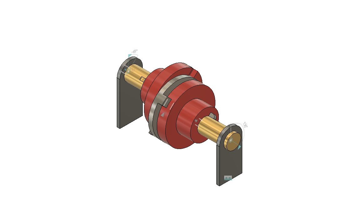
Credits - Autodesk
This type of coupling is used where shafts are parallel at a small misaligned distance. Both positions are both slots could connect. This coupling made with circular disk with projections either side. Torque transfer takes place due to motor and equipment shafts connected through circular disk in coupling.
Application
Printing applications
Universal coupling
Universal coupling is used where shafts are at some angle. The inclination shaft may be increase while in rotation. This type of coupling is used in automobile industry as knee type joints.
Application
Generally used in Automobile Driver shaft and aircraft.
Check points of Couplings
1. All parts of coupling must be tight enough so decoupling and misalignment should be avoided.
[In reactors it will be critical and in exothermic, polymer reactors it becomes worst, In continuous process decoupling of pump may leads in unusual stoppage of plant.]
2. Whenever Preventive maintenance or shutdown takes place alignment checking should be done through laser alignment technique


